The KAPtery closed on December 31, 2024. Products can no longer be ordered from these pages. Some products are available for purchase from Ennapurna in France. For questions, replacement parts, special requests, or leftover inventory, use the Contact page above.
Shutter Timer Kit
 |
|||
|---|---|---|---|
 |
 |
 |
 |
 |
 |
||
OUT OF STOCK
Sorry! We'll work to get this item back in stock as fast as possible. Please check back soon, and thanks for your patience.
Check the Public Lab Store for this product, or consider using the more capable SkyShield AutoKAP controller.
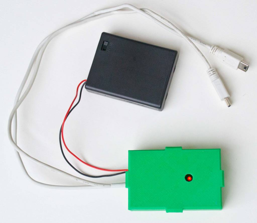
This kit will build the shutter timer that is available ready to fly here. Components must be soldered to the circuit board, and USB cables must be modified for connecting to the board. The finished board fits in a 3D printed case for mounting on an aerial camera rig.
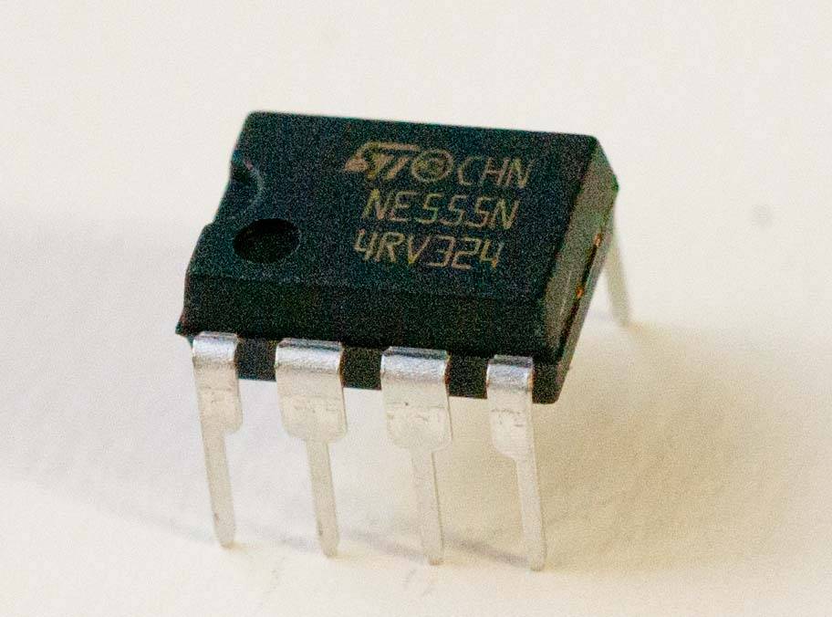
This kit includes an MK111 timer kit based on the 555 IC. The circuit outputs 5 volt pulses to the USB ports of Canon PowerShot cameras to synchronize the release of their shutters. When the remote function of CHDK is running on both cameras, the start of a pulse to the USB ports activates a "half press" of the shutter button and all automatic focusing, exposure, etc is done. When the pulse ends, the shutters of both cameras operate simultaneously to take perfectly synchronized photos. The timer allows adjusting both the interval between pulses (2.5 to 60 seconds) and the duration of the pulses (0.5 and 5 seconds). An indicator LED is lit during the pulse.
This timer allows two-camera infrared systems to take synchronous pairs of normal and near-infrared photos for combining into false color IR or NDVI images. This is the timer included in all Titan 2 IR packages here. Synchrony is critical when the cameras are moving if the photo pair must be aligned to make a composite image.
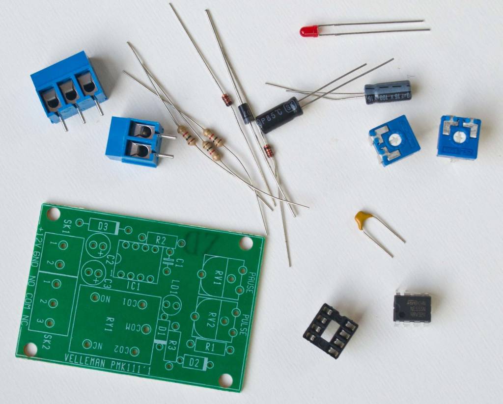
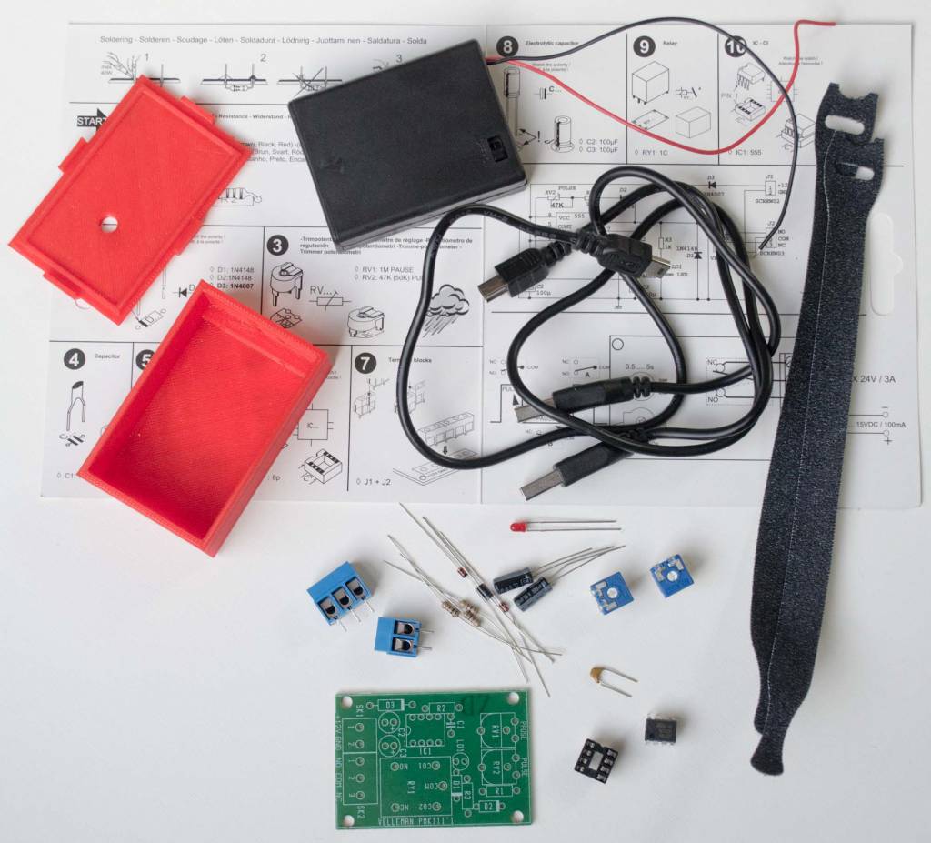
Includes circuit board and components, 3D printed enclosure, battery box with on/off switch (for four alkaline AAA, not included), two Mini-B USB cables, two Velcro ties, jumper wire, heat shrink tubing, lock washers, Velcro tape for the case bottoms, and the MK111 assembly instructions and specification sheet.
Modifications from the included instructions allow the timer to operate on low power. The electromagnetic relay (which controls a separate power source) is not installed (and is not included) and two jumper wires are connected. Instead of needing two power sources, the batteries that power the timer also provide pulses to the cameras. Any six volt source can power the device, so the very small 4LR44 battery will work. Alkaline AAA batteries are easier to find and four of them will trigger two cameras every eight seconds for many hours.
Total flying weight with batteries is 125 grams.
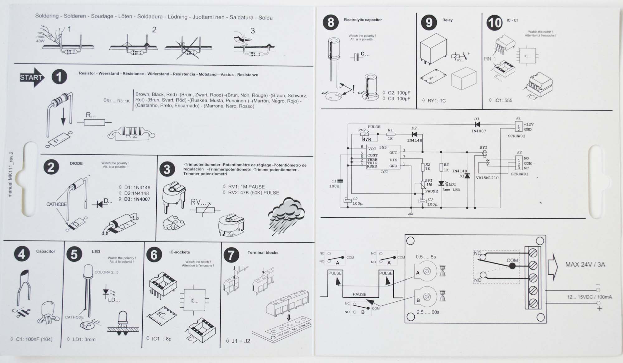 |
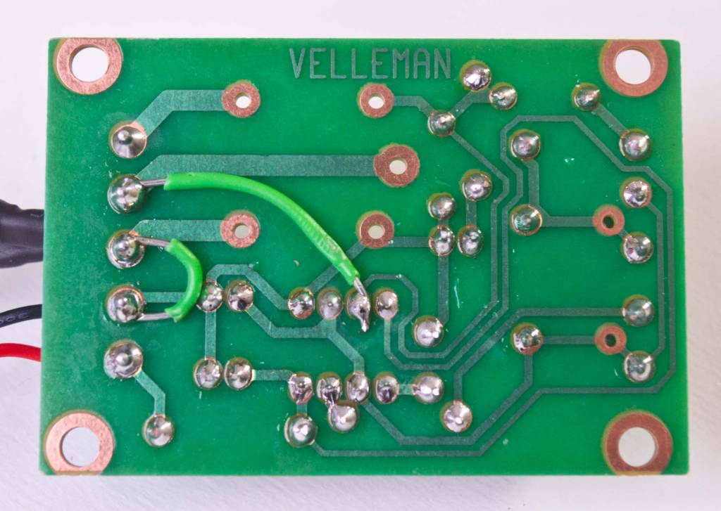
| Soldering the components to the PCB is straightforward. Step #9 is skipped as the relay is not needed. |
A full assembly guide can be downloaded here: Shutter Timer Guide
Assembly time: 2 hours
Key steps in assembly
- Solder the components as described in the included instruction sheet, but skip step nine so no relay is installed. Save a few of the leads snipped off the components.
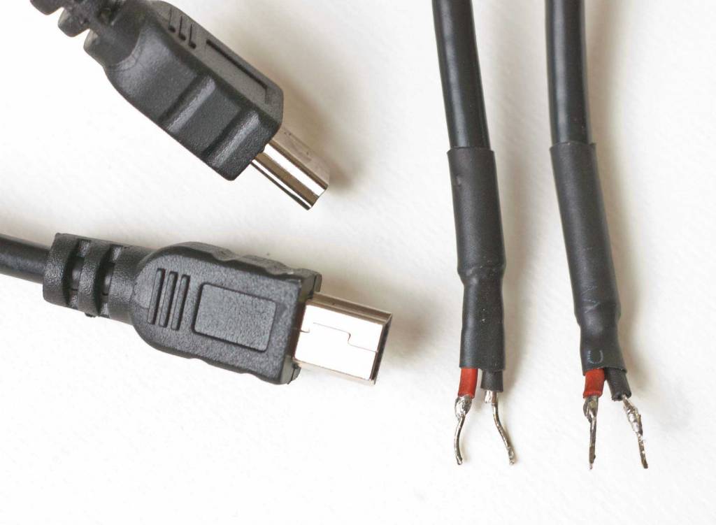
- On the underside of the PCB solder two jumper wires as shown in the photo above.
- Cut the large USB A connector off the USB cable and strip the ends of the red and black wires.
- Solder a stiff wire about 1 cm long onto the ends of the red and black wires to strengthen them (see photo). Use pieces of the component leads that were snipped off as the timer PCB was assembled.
- Stiffen and insulate the cable ends with heat shrink tubing.
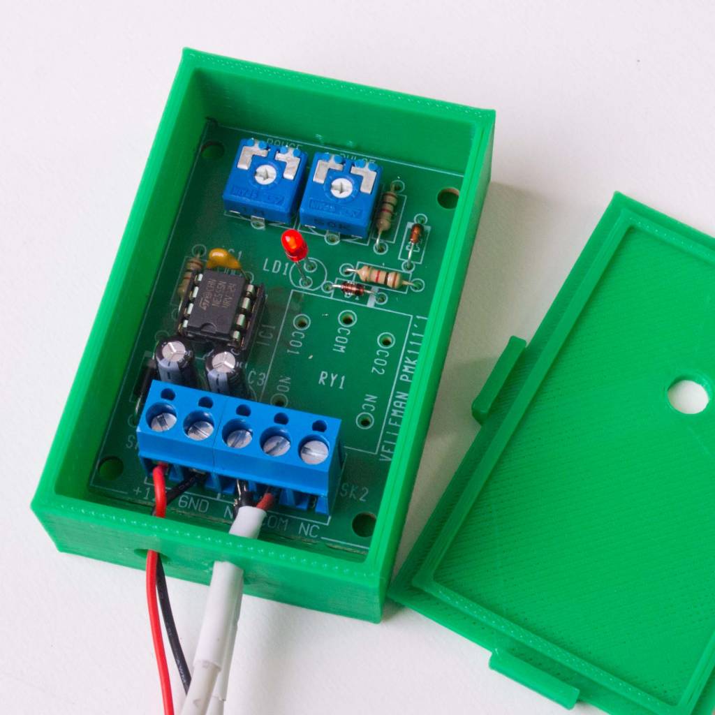
- Pass the USB and battery cables through the ports in the 3D printed case, through a bent lock washer, and into the appropriate terminal block.
- Battery: red wire to +12V, black wire to GND.
- Both USB cables: red wires to COM, black wires to NO.
- Tighten the screws to hold the wire ends firmly.
- Squeeze the washers around the wires up against the inside of the plastic case to prevent the wires from being pulled out of the terminal blocks.
- Install four fresh alkaline AAA batteries in battery case and turn switch to ON.
- Use a small screwdriver to turn the white slot at the center of the potentiometers ("PAUSE" and "PULSE") to set pulse interval and length.